Opis
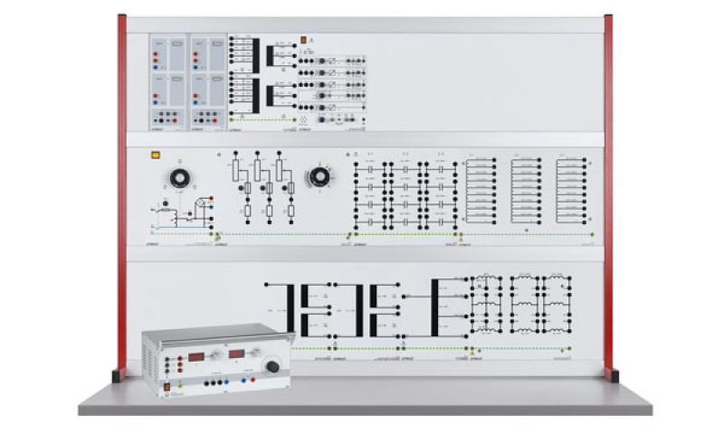
The experiments are carried out using transformers on experiment panels in panel frames.
Objectives
- Protective measures and electrical safety
- Set-up of power generation systems according to circuit diagrams
- Use of commercial hand-held multimeters
Transformers are magnetically coupled systems used for transforming AC voltages or matching impedance. Transformers can therefore be used primarily for measurement or generation of electric power. These practical exercises study exclusively transformers used in energy generation. Transformer power ratings can range from a few mVA up to several MVA. The size and design also have an important effect on the transformer ratings. Transformers are regarded as electrical machines even though they contain no moving parts. The windings of three-phase transformers can be connected in a variety of circuit configurations.
A toroidal transformer is ring-shaped. The material used for the core can be soft iron or ferrite material. The shape means that there is very little magnetic scattering. However, the manufacturing process of the windings is more complex than in conventional transformer types. The switch-on current for toroidal transformers can be very high and in practice needs to be limited by suitable means.
Students carry out the experiments as specified in the printed manual. Hand-held multimeters are used to measure the characteristics of the transformers. The graphical representation of the time course of the current and voltage is not essential. Thus multimeters are sufficient for measuring RMS values.
This individual equipment set allows for measurement of toroidal transformers under load (resistive, inductive, capacitive).
The target group is made up of commercial apprentices and students of power engineering. The course offers experiments at an intermediate level for vocational colleges and undergraduate level.
The equipment set utilises the 0.3 kW toroidal transformer and for economic reasons, it employs the 1.0 kW resistive load.
Topics
- Voltage equation and equivalent circuit
- Measurement without load, with load and with a short circuit
- Determination of self-inductance, magnetic coupling and leakage
- Losses, changes in voltage and efficiency
Similar to illustration
| 733 98 | AC toroidal core transformer 0.3 | 1 |
| 733 10 | Resistive load 1.0 | 1 |
| 732 41 | Capacitive load 0.3 | 1 |
| 732 42 | Inductive load 0.3/1.0 | 1 |
| 531 282 | Multimeter Metrahit Pro | 3 |
| 727 12 | Power factor meter | 1 |
| 726 09 | Panel frame T130, two-level | 1 |
| 726 85 | Adjustable transformer 0…260 V | 1 |
| 500 59 | Safety bridging plugs, black, set of 10 | 2 |
| 500 591 | Safety bridging plugs, yellow/green, set of 10 | 1 |
| 500 851 | Safety connecting leads, 32 A, set of 32 | 1 |
| 500 852 | Safety connecting leads, 32 A, yellow/green, set of 10 | 1 |
| 569 2001L | LIT: Transformers (in German) T 10.1 | 1 |
| 569 2001S | LIT: Transformers (in German) T 10.1 | 1 |
| 569 2002 | * LIT: Transformers (in English) T 10.1 | 1 |
Articles marked with * are not essential, we do however recommend them to carry out the experiment.


