Oscyloskop cyfrowy GDS3354 4x350MHz 5GSa/s, 8 cali

Opis
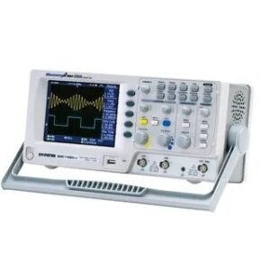
Oscyloskop cyfrowy GDS3354 4x350MHz 5GSa/s, 8 cali
Firma GWInstek wprowadza nowa serię oscyloskopów cyfrowych GDS-3000 z próbkowaniem w czasie rzeczywistym do 5GSa/s (100GSa/s EQ) oraz pasmem częstotliwości do 350MHz. Oscyloskopy charakteryzuje również technologia wyświetlania przebiegów VPO, okno narzędzi nawigacji, pomiary mocy, testowanie i pomiary I2C/SPI/UART. Duży 8 calowy wyświetlacz SVGA 800×600 umożliwia przedstawienie do 4 kanałów na oddzielnych oknach. Seria GDS-3000 uzupełnia aktualną ofertę oscyloskopów firmy GWInstek co umożliwia wybór odpowiedniego oscyloskopu biorąc pod uwagę parametry oraz cenę.
W serii GDS-3000 dostępne są pasma częstotliwości 150MHz, 250MHz oraz 350MHz przy 2 lub 4 kanałach analogowych. Pamięć 25k punktów na każdy kanał, próbkowanie do 5GSa/s oraz 3,000 ramek/sek. Zaawansowane wyzwalanie między innymi Video, Pulse Width, Runt, Rise Time & Fall Time, Alternate, Delay by Time, Delay by Event, oraz Hold-Off. Funkcja AUTORANGE dla podstawy czasu oraz odchylania pionowego umożliwia dokładne wyświetlenie oczekiwanego przebiegu. Dostępny ZOOM wraz z podglądem na aktualną pozycje powiększenia.
W ostatnich latach projektanci zasilaczy zwiększali ich stabilność oraz wydajność jednak bez użycia specjalistycznego sprzętu. Aktualnie oscyloskopy GDS-3000 umożliwiają testowanie systemów zasilaczy, pomiary jakości energii, harmonicznych, tętnienia, prądu rozruchu oraz wiele innych pomiarów dostosowanych do potrzeb inżynierów. W opcji dostępne są wysokonapięciowe sondy różnicowe oraz sondy prądowe. GDS-3000 w standardzie wyposażone są interfejsy RS-232, LAN, VGA, USB host/device, USB flash port oraz funkcję PictBridge. Darmowe oprogramowanie Freewave umożliwia pełne pomiary online na PC. Aby rozszerzyć możliwości menu oraz pomoc w oscyloskopie dostępne są również w języku polskim. Oscyloskopy podlegają 3 latniej gwarancji. W standardzie dostarczane są z certyfikatem kalibracji producenta.
Charakterystyka:
- Pasmo 350/250/150MHz, kanały 2 lub 4
- Szybkośc próbkowania 5GSa/s RT lub 100GSa/s ET
- Niezależna pamięć dla każdego z kanałów
- VPO Technology
- Duży 8-calowy wyświetlacz o rozdzielczości 800×600
- Funkcja wyświetlania przebiegów z każdego kanału w oddzielnych oknach
- Wbudowane 3 impedancje (50Ω/75Ω/1MΩ)
- Opcjonalne oprogramowanie do analizy mocy (Opcja)
- Serial Bus Analysis Software for I2C, SPI and UART (Opcja)
The GDS-3000 Series is a new platform of 4-input channels, 500MHz bandwidth, 5GSa/s sampling rate, and VPO waveform display. The split screen feature has been designed to meet the requirements of multi-window & multi-signal tests in the research and the manufacturing fields. The optional power analysis software and the optional serial bus analysis software are available to facilitate the engineer’s tasks in testing and manufacturing of the associated products.
Three new differential probes, GDP-025, GDP-050 & GDP-100, and two new current probes, GCP-005 ,GCP-020 ,GCP-100 and GCP-530 & GCP-1030, are coming along with the GDS-3000 Series to provide total solutions for a wide variety of applications in the industry, service and education market sectors. The GDS-3000 Series, a high-tech platform carrying thoughtful features, brings very high customer value to both general purpose market and professional market.
VPO- Visual Persistence Oscilloscope Signal Processing Technology

UNIQUE SPLIT SCREEN FUNCTION

The unique split screen feature of GDS-3000 Series allows each input channel to be operated independently with respective setting and waveform display. The time base, the vertical sensitivity, and the trigger selections can be done by each channel separately, and the waveform of each input signal can be shown on the individual part of the screen. This nearly four-DSO-in one feature is very useful for the applications that need to simultaneously see the details of multiple waveforms with very different characteristics. The 8-inch high resolution 800×600 LCD display makes the split screen a pleasant observation environment to view the details of complex signals.
COMPLETE SET of TRIGGER FUNCTIONS
Besides Edge trigger, the GDS-3000 Series also offers various trigger functions, including Video, Pulse Width, Runt, Rise Time & Fall Time (specific time length), Alternate, Delay by Time, Delay by Event, and Hold-Off. The high sampling rate, the VPO signal processing & display, and the flexible trigger function all together make the GDS-3000 Series a powerful tool for waveform capture and display of various types of signals.
AUTO RANGE FOR BOTH TIME BASE AND VERTICAL SCALE

The Auto Range function automatically adjusts the time base and/or the vertical scale of displayed waveform when the frequency and/or the amplitude of input signal changed. This function gives user the convenience to have DSO always display waveform in a proper fashion on the screen tracking the frequency and amplitude changes of the input signal. It is especially useful when the user needs to alternately probe and test multiple circuit points containing signals with different frequencies and amplitudes.
DUAL DISPLAY WINDOW ZOOM

The GDS-3000 Series Window Zoom function provides dual display mode to show the main waveform and the magnified section of zoomed-in waveform at the same time. Under „Zoom” mode, the width and the position of zoom-in window over the main waveform can be selected to get the magnified waveform as needed for detailed observation. To quickly and accurately move the zoom-in window to the expected position, the „Coarse” mode helps move the window to the needed position immediately and the „Fine” mode provides fine adjustment to precisely place the window in the exact position.
28 AUTOMATIC MEASUREMENTS

The GDS-3000 Series supports simultaneous measurement of up to 28 waveform measurement items grouped into three main waveform parameters: amplitude, time and delay measurements. The display modes include an individual mode and a Display All mode. The former can display any 8 of the automatic measurements while the later can display all the automatic measurements for a channel.
FFT TEST FUNCTION

To observe fundamental and harmonic frequency components of a signal, the FFT function on a digital storage oscilloscope is often used. Typically the traditional unit of the FFT is decibel (dB). However, when using dB it is sometimes difficult to identify the fundamental frequency of a signal from a noisy spectrum. With FFTrms function, the GDS-3000 Series can clearly display the fundamental frequency of an acquired waveform.
The FFT function of GDS-3000 supports Rectangular, Hamming, Hanning, and Black-harris windows.
THREE INPUT IMPEDANCE SELECTIONS

Three input impedance, 1M , 75 , and 50 are available for user’s selection. The flexibility of impedance selections, including 1M to get minimum loading effect, 75 to accommodate Video transmission applications and 50 to fit RF communication applications, extends the GDS-3000 Series utilization range.
X-Y MODEX-Y MODE


The GDS-3000 Series allows future installation of additional application software at the user site. This provides an open environment for optional software upgrade and additional feature built-in in whenever the GDS-3000 Series user has the need. The flexibility of software installation platform keeps the DSO being in use always up-to-date.
WAVEFORM FILE PREVIEW

The GDS-3000 provides an optimized operation interface for viewing screen captures. Generally, the oscilloscope may store large amounts of waveform data after a long period of time. To help prevent engineers from selecting the wrong file from a large number of stored waveform files, the screen capture preview function can be used to preview the waveform file without opening files so that operation of the oscilloscope is more efficient and convenient.
FREE REMOTE CONTROL SOFTWARE

Using a USB port coupled with FreeWave remote monitoring software is the easiest and most convenient way to capture data from the GDS-3000 Series. With FreeWave, a screenshot can be saved as an image file (.bmp/.jpg), waveform data (.csv) can be logged and movie files(.wmv) can be recorded in real-time. Not only can FreeWave monitor and record waveforms over a long period of time, but previously recorded waveforms can also be observed. Instrument settings can even be configured without the need to learn incomprehensible command line syntax. With the simple user interface and robust features, FreeWave allows you to get the most out of the GDS-3000 with little effort.
VARIOUS INTERFACES SUPPORT

Two high-speed USB 2.0 Host ports located in both front panel and rear panel are used for easy access of stored data. In the rear panel, a USB Device port is available for remote control and hardcopy print-out through a PictBridge compatible printer. RS-232 and LAN interfaces are provided as standard for system communication & ATE applications. A SVGA video output port allows the transfer of DSO screen image to an external projector or monitor for remote monitoring or big screen observation. A GPIB to USB adaptor is available as an option for interface conversion though the USB Device port in the front panel.
SERIAL BUS ANALYSIS SOFTWARE SUPPORTING I2C, SPI and UART (OPTIONAL)
Serial Bus Analysis Software

The GDS-3000 Series provides two dedicated key

With serial bus technology being widely used in embedded applications, the proper triggering and analysis of flowing data, control signal and associated pulse waveforms in serial bus communication has been a difficult job and challenge to design engineers. The Serial Bus Analysis software of GDS-3000 Series carries complete analysis tools for triggering and decoding of commonly used serial bus interfaces, including I2C, SPI and UART. Without spending time to study serial bus regulation details, the user only needs to set the trigger condition on GDS-3000 to get the data slots of interest.
POWER ANALYSIS SOFTWARE FOR POWER SUPPLY MEASUREMENTS (OPTIONAL)
Power Quality

Harmonics

Ripple

In-rush Current

The Power Analysis software contains four measurement functions, including Power Quality, Harmonics, Ripple and Inrush Current. The Power Quality analysis function allows the measurements of Voltage, Current, Frequency, Power and other quality related parameters for power source efficiency improvement. The Harmonics analysis function performs evaluation of power waveform distortion and gives harmonic test data for power source design and quality check. This function is complied with IEC 61000-3-2 standard. The Ripple measurement function, acquiring the ripple and noise overriding the DC waveform, is used to evaluate the DC power source quality. The Inrush Current measurement function is used to measure the power-on surge current, which may cause the damage of the device circuit.
Marka
GW Instek