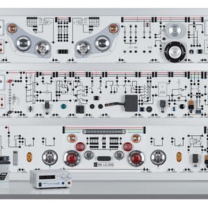
Płytka ćwiczeniowo projektowa do układów CPLD/FPGA – FPT-1
Opis
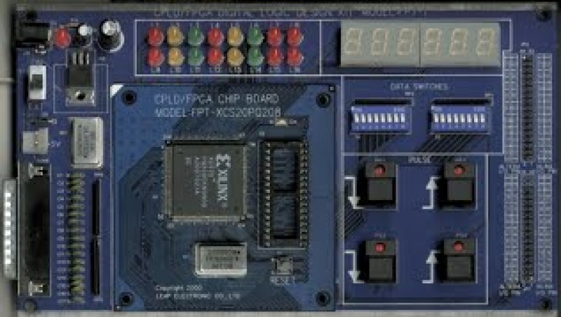
CPLD/FPGA Logic Circuit Design Experimental Kit
Introduction
In the past, each engineers themselves need to design their own circuit board, which then need a certain amount of universal bread boards and logic components to do trials and errors, all this not only wastes time, also expenses would increase. Now an electronic engineer can finish circuit designs easily by using CPLD / FPGA, only by a few reformation of the software it can be ready for operations.
Leap Electronic have considered for the beginners' needs, therefore we have invented FPT-1 combining the CPLD or FPGA for educational purposes. The FPT-1 avoids the soldering issues between the circuits and cable lines.
Features
- Use CPLD/FPGA software and hardware to design Logic IC, in order to replace complicated hardware design of TTL/CMOS.
- Capable in using Circuit Graphic and digital hardware descriptive syntax (VHDL, ABEL, and AHDL) to develop circuits, and directly download from original manufacturer’s software via printer port.
- Modularized design: user can choose ALTERA or XILINX chipboard module.
- Avoid the soldering issues between the circuits and cable lines.
Test Content
Combined logic design, simulation and test
- Basic logic
- Deducted
- Decoder
- Combined logic
- Comparator
- Multiplexer
- Adder
- Compiler
- Demultiplexer
Sequential logic circuit design simulation and test
- Flip-Flop
- Shift register
- Shift counter register
- Synchronized counter
- Non-Synchronized counter
Thematic Application Test
- Digital clock
- Counter
- Electronic alarm clock
- Traffic light control
- Electronic dice
- VHDL/AHDL design
- Random design of expanded I/O Pin
Application Program Range
- Fundamental logic
- Digital circuit design
- Digital system design
- Microprocessor principle
- CPLD/FPGA chip design
Chip board specification
-
Device supported:
ALTERA: EPF10K10TC144 (TQFP144 pin)
XILINX: XCS10TQ144(TQFP144 pin) -
Chip board model:
ALTERA: FPT-EPF10K10TC144
XILINX: FPT-XCS10TQ144 - 8 x 2 LED shown output.
- 8 x 2 Logical input toggle.
- 4 pulse keystrokes producer (two positive pulses:two negative pulses).
- 6 digits and 7 nodes monitor.
- Own red main power guiding lights.
- Within 10MHz oscillator.
- Own main power switch to exchange adaptor with Extend Power Pin.
- 25pin D Type Connector (Printer Port Download FPGA).
- Use DC 9V adaptor or Extend Power Pin provided for user. Specification: DC 5V.
- Support ALTERA MAX +Plus II Baseline and XILINX Foundation’s development system.
- Not use expanded area I/O Pin, provided user definition use.
PC System Requirement
- Operating System: Refers to the original CPLD / FPGA software install requirement.
Standard Accessories
- FPT-1 Main board x1
Optional Accessories
- DC 9V/500mA power adaptor x 1
- 25-pin printer cable x 1

