Zestaw ćwiczeniowy – Wykorzystanie energii GTU 104 / poprawa współczynnika mocy / pomiar oraz taryfy energii
Opis
|
SYMBOL |
SPECYFIKACJA |
ILOŚĆ |
|
|
ZESTAW ĆWICZENIOWY ENERGETYKA GTU104.1 ORAZ GTU104.2 |
|
|
|
Kompletny zestaw ćwiczeniowy energetyka GTU104 składa się ze stołu, zestawu modułów eksperymentalnych oraz zestawu przyrządów pomiarowych. |
|
|
|
Zestaw ćwiczeniowy obejmuje zagadnienia: |
|
|
GTU104 |
Odbiór energii |
|
|
|
Poprawa współczynnika mocy |
|
|
|
Poprawa współczynnika mocy biernej dla obciążeń indukcyjnych |
|
|
|
Demonstracja automatycznej regulacji współczynnika mocy biernej |
|
|
|
Pomiar energii oraz taryfy |
|
|
|
Pomiar zużycia energii czynnej |
|
|
|
Pomiar zużycia energii biernej |
|
|
|
Pomiar max zapotrzebowania na energie |
|
|
|
Demonstracja odcięcia obciążenia |
|
|
|
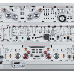
Charakterystyka zestawu: Metalowe obudowy modułów Typy przyrządów panelowe lub stacjonarne Izolowane modułu instalowane na ramie Moduły umozliwiaja łączenie obwodów z odrębnymi komponentami elektrycznymi oraz przyrządami pomiarowymi Moduły na panelu przenim posiadaja schematy elektryczne Komponenty elektroniczne oraz moduły łączone za pomoca bezpiecznych przewodów z izolowanymi wtykami bananowymi Poniżej lista modułów oraz elementów stanowiąca kompletne wyposazenie żestawu ćwiczeniowego ENERGETYKA GTU104.1 lub GTU104.2 – wykaz z pliku PDF |
|
|
DL 1017R |
RESISTIVE LOAD – didactic equipment It must consist in a single or three-phase resistive step-variable load. Housed in a metallic box. MECHANICAL FEATURES The load shall be composed of a rugged metal structure and of a front metal panel. On the front panel all the controls, the protection, the output terminals and a clear synoptic diagram, shall be collected. ELECTRIC FEATURES The load shall be composed of resistances, with possibility of star, delta and parallel connection, controlled by three switches. This item must be provided also with fuses protection. As a function of the switch positions, there shall be the following phase values: Position Resistance Max power per phase 1 1050 Ohm 46 W 2 750 Ohm 65 W 3 435 Ohm 110 W 4 300 Ohm 160 W 5 213 Ohm 230 W 6 150 Ohm 330 W 7 123 Ohm 400 W Maximum power in single or three phase connection must be 1200 W. Rated voltage in star connection must be 380 V, in D connection must be 220V, in single-phase must be 220V. 4 mm. safety terminal included on the front panel for the electrical connection. |
1 |
|
DL 1017L |
INDUCTIVE LOAD – didactic equipment
It must consist of a single or three-phase inductive step-variable load. Housed in a metallic box. The load shall be composed of a rugged metal structure and of a front panel. On the front panel all the controls, the protections, the output terminals and a clear synoptic diagram, shall be collected. ELECTRICAL FEATURES The load shall be composed of inductances, with possibility of star, delta and parallel connection, controlled by three switches. This item must be provided also with fuses protection. As a function of the switch position there shall be the following phase values. Position Inductance Max. Power per phase 1 4.46 H 34 VAr 2 3.19 H 48 VAr 3 1.84 H 83 VAr 4 1.27 H 121 VAr 5 0.90 H 171 VAr 6 0.64 H 242 VAr 7 0.52 H 297 VAr Max reactive power 890 VAr in three-phase or single-phase connection. Rated voltage in star connection must be 380V, in D connection must be 220V, in single-phase must be 220V. 4 mm. safety terminal included on the front panel for the electrical connection. |
1 |
|
DL 1021 |
SQUIRREL CAGE THREE-PHASE ASYNCHRONOUS MOTOR – Didactic equipment:
Induction motor with three-
Technical features: Power: 1.1 kW – Voltage: 220/380 V D/Y – Current: 4.7 / 2.7 A D/Y – Speed: 2800 rpm, 50 Hz It must be supplied with a hooked module in aluminum with PVC label and safety terminals for the electrical connection.
A schematic diagram must be shown on the hooked module. – Plate that brings its axis height to the standard measure (112 mm). – Plates for fixing to the base of the machine
– Four screws for fixing of the machine The motor must be supplied with a theoretical and practical manual in English language. |
1 |
|
DL 1019P |
POWDER BRAKE – Didactic equipment: Provided with water level, arms, weight and balance weight for measuring the output torque of the motor. Possibility of assembling a load cell. Technical features Rated power: 1.1 kW at 3000 min-1 Maximum speed: 4000 min-1. It must be possible to couple the electrical machine with other electrical machines through a hub and spider elastic gear ring in polyurethane. It must be supplied with a hooked module in aluminum with PVC label and safety terminals for the electrical connection.
A schematic diagram must be shown on the hooked module. – Plates for fixing to the base of the machine
– Four screws for fixing of the machine The brake must be supplied with a theoretical and practical manual in English language. |
1 |
|
DL 1054TT |
BRAKE CONTROL UNIT – Didactic equipment: control unit for the power brake. It must allow measuring the rotating speed and the torque generated by an electrical motor. It must also provide the excitation voltage to the brake. The speed and the torque are displayed by means of pointer instruments; analogue outputs must also be available. Speed section: 40 division instrument, class 1.5, ranges: 2000 – 4000 – 6000 min-1, with switch. Torque section: 50 division instrument, class 1.5, ranges: 10 – 20 Nm, with switch, Power supply section for the brake: Output: from 0 to 20 Vdc, 1 A, Supply voltage: 230 V, 50/60 Hz – 4 mm safety terminals and 2 mm terminals for the electrical connection must be included. |
1 |
|
DL 2006E |
LOAD CELL – Didactic equipment.
Resistance electronic strain-gauge with 150 N range must be mounted on the The cell shall work by flexure, and the outgoing electric signal shall be proportional to the applied force and to the supply voltage. The cell shall be made up by special steel and must be OIMLR60 directive compliant. Combined error: < ±0.05%. IP65 compliant Technical Features: Rated output 3mV/V ±5% CREEP at nominal load in 30 minutes 0.05 % Max supply voltage without damage 10 Volt Input resistance 410Q ±40 Output resistance 350 Q ±5 Zero balance ± 2 % Insulation resistance >2000 M Q Safe overload (% of Full Scale) 150 % Ultimate overload (% of Full Scale) > 200 % Deflection at nominal load 0.5 mm Temperature:
Temperature effect on zero 0.005% °C The unit must be supplied with a manual in English language.. |
1 |
|
DL 2031M |
OPTICAL TRANSDUCER – Didactic equipment:
suitable to measure the revolving speed through a slotted optical
Supplied with connector for the transfer of the signal to the electronic tachometer. Prearranged for its assembling on the machines of the laboratory. |
1 |
|
DL 1013A |
UNIVERSAL BASE – Didactic equipment:
this item must consist of a steel alloy varnished structure mounted on anti- vibration rubber feet, provided with slide guides for the fixing of one or two machines and with a coupling guard. -Light alloy base, leveled on the upper supporting planes, with two guides for all the couplings of machines rated 1 kW
In the lower section high sensitivity shock absorbers must be mounted, arranged to be fixed to a supporting plane. -Flask for the blocked rotor test in varnished light alloy |
1 |
|
DL 2108TAL -SW |
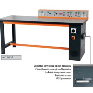
THREE-PHASE SUPPLY UNIT – Didactic equipment: Power supply unit for three-phase connection with 4-pole cam mains switch. 25 A current operated earth leakage circuit breaker, sensitivity 30 mA.
Triple-pole motor protection switch: 6.3 to 10 A. L1, L2, L3, N and PE. Switch for simulation of wind or photovoltaic energy power source 4 mm. safety terminal included on the front panel for the electrical connection. |
1 |
|
DL 2108T02 |
POWER CIRCUIT BREAKER – Didactic equipment: Three-phase power circuit breaker with normally closed auxiliary contact. Features: Contact load capability: 400 Vac, 3 A Supply voltage: single-phase from mains Power circuit: Insulation voltage: 750V Thermal current : 20A Auxiliary contact: Insulation voltage: 750V. Rated current: 3A Auxiliary power: Single-phase voltage 220V, 50-60Hz It must be possible to control manually the power breaker switch using the push-buttons “on”and “off” or externally via the switching contact PLC or RELAY. This power contacts state shall be indicated by leds: Green led = open contacts. Red led = closed contacts. While at SIGNAL OUTPUT terminals will be available a TTL level: Low level ( 0V )= open contacts. High level ( 5V )= closed contacts. The RS flip-flop state shall be indicated by a led: Yellow led = set flip-flop. 4 mm. safety terminal and 2 mm. terminals included on the front panel for the electrical connection. It must be supplied with manual in English language |
4 |
|
DL 2108T19 |
REACTIVE POWER CONTROLLER – Didactic equipment:
module with insulated panel, reactive power controller for automatic adjustment of the power factor in systems with inductive load. Power factor range -0,7 … 0 … 0,7 Step 1 … 7 programmable Outputs for external contactors 4 Contactor power 250V 10A Line current max 5A On the front panel, it must include the following elements: Operation indicator Wanted power factor adjustment Relays switchover time adjustment Number of connected capacitors adjustment Number of phases adjustment Key to enter the setup menu Key to diminish the parameter values Key to increase the parameter values Key to confirm the values set Display System anomalies indicator Inductive load indicator Capacitive load indicator Excited relays indicator 4 mm. safety terminals included on the front panel for the electrical connection. |
1 |
|
DL 2108T20 |
SWITCHABLE CAPACITOR BATTERY – Didactic equipment: Switching system with which different capacitance values must be connected to the mains for reactive power compensation Four switching levels each consisting of 3 capacitors in star connection with discharging resistors: • level 1 (b1 coil): 3 x 2 μF/450 V • level 2 (b2 coil): 3 x 4 μF/450 V • level 3 (b3 coil): 3 x 8 μF/450 V • level 4 (b4 coil): 3 x 16 μF/450 V Compensation power: max 1360 VAr at 50 Hz, 380 V It must be possible to control separately each switching level: • internally, through 4 toggle switches • externally, through 4 control inputs Coil operating voltage: 220 Vac It must be possible to use the module with internal and external control. This module must have insulated front panel with the electrical scheme; it must include also 4 mm. safety terminals. It must be supplied with manual in English language |
1 |
|
DL 2109T2A5 |
MOVING COIL AMMETER MODULE – didactic equipment
This module must be suitable for ac and dc current measurements. •Scale: 50 divisions – the scale shall made open and reasonably uniform down to about 20 percent of the full-scale reading.
•Range: 2.5 A – 1.25 A
This module must have insulated front panel, 4 mm. safety terminals, one selector and one analog meter. |
2 |
|
DL 2109T3PV |
MOVING IRON VOLTMETER MODULE – didactic equipment
This module must be suitable for ac and dc voltage measurements.
•Scale: 50 divisions – the scale shall be made open and reasonably uniform down to about 20% of the full-scale reading. This module must have insulated front panel with the electrical scheme, 4 mm safety terminals, fuse protection and one analog meter. One selector shall be included in this panel. The module must be supplied with manual in English language. |
1 |
|
DL 2109T26 |
POWER METER – Didactic equipment : This module must consist in a demonstration single-phase meter for active power and capacitive/inductive reactive power. Technical features: Measurement ranges: Voltage: 3/10/30/100/300/1000 V Current: 0.1/0.3/1/3/10/30 A Frequency range: Active power: 0 … 20 kHz Reactive power: 50 Hz LED indicators: capacitive reactive power, inductive reactive power, overload voltage (with acoustic sound), overload current (with acoustic sound). Auxiliary supply: single-phase from mains This module must have insulated type front panel with the electrical scheme and also 4 mm safety terminals. Two selectors, one switch and one push-button shall be included in this panel. |
2 |
|
DL 2109T27 |
POWER FACTOR METER – Didactic equipment: The module must consist of one single-phase power factor meter with measurement of the power factor and phase-angle with ranges: power factor: 0 cap to 1 to 0 ind, phase-angle: -90°cap to 0 … +90°ind. Measurement ranges: voltage 3 / 10 / 30 / 100 / 300 / 1000V Current 0.1 / 0.3 / 1 / 3 / 10 / 30A Frequency range: active power 0…20 kHz reactive power 50Hz Led indicators: capacitive reactive power inductive reactive power overload voltage, with acoustic sound overload current, with acoustic sound Auxiliary supply: 220V, 50-60Hz 4 mm safety terminals for electrical connections included. It must be supplied with manual in English language. |
1 |
|
DL 2109T29 |
MAXIMUM DEMAND METER – didactic equipment
The module must consist of a microprocessor controlled three-phase power analyzer. It must have insulated panel and it must be suitable for the measurement of voltages, currents, frequencies, active power, reactive power, apparent power.
On the front panel, it must include a RS485 port, a on/off switch and LCD display with the following features: The module must be supplied with manual in English language |
1 |
|
DL 2109T34 |
ACTIVE AND REACTIVE ENERGY THREE-PHASE COUNTER – Didactic equipment : module with insulated panel, microprocessor controlled three-phase power analyzer. Measurement of voltages, currents, frequencies, active power, reactive power, apparent power. Connection: Three-phase – 3 or 4 wire – Reference voltage, Un: 230 (400)V…240 (415)V – Limit range of operation: 110 (190)V…254 (440)V – Basic current, In: 10A – Maximum current, Imax: 63A – Communication: RS485 galvanically insulated from input meas.
Display type: LCD Backlit, 8 digit – Active energy: Total, Partial (resettable) or Double tariff – Reactive energy: Total, Partial (resettable) or Double tariff – Power: Active, Reactive, Apparent, max. demand 4 mm safety terminals for electrical connections included. |
1 |
|
DL CRON |
Electronic stopclock with LCD display |
1 |
|
DL 2100T2 |
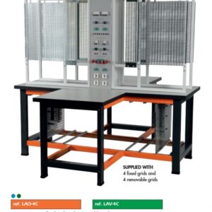
TWO LEVEL FRAME WITH TABLE Metal frame for fitting the modules of the laboratory. Mounted on a bilaminated wooden top of a table. Metal square legs with compensating feet which can be adjusted to offset the uneveness of the floor. |
1 |
|
DL 2100TA |
STORAGE CABINET Fire varnished steel-plate, provided with shelves for module storage and key-locked doors. Supplied with 4 rubber casters, the cabinet should be fitted under the experimental table |
1 |
|
DL 1155GTU |
A set of cables with at least 80 connecting leads with security plugs of different colours, length and sections. |
1 |