Opis
A2.4.1.4 Komputer pokładowy
| Traditional monitoring of fill levels and temperatures occurs with modern control units. Current measurements in conductor loops give information on a worn brake pad.
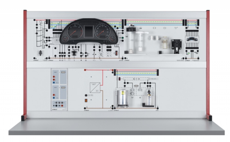
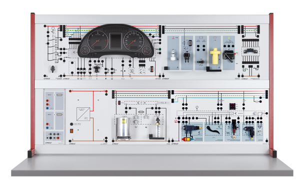
Moreover, various fill level sensors provide data that is shown to the driver optically and/or acoustically. The „on-board computer” educational system monitors:
|
||
| The oil sensor is a continually measuring thermal oil level and oil temperature sensor (TOG) that can be filled with motor oil. Optionally, regulation resistors can simulate the signals. The signal produced converts the information on the oil into a combined PWM (pulse-width modulation) and PFM (pulse-frequency modulation) signal, that Sensor-CASSY can chart, for example. | ||
| The signal from the coolant’s temperature sensor can also either triggered either by immersion into warm water or by setting a potentiometer. An appropriate holder is available for parallel temperature measurement with a temperature sensor (666212). In the uncoupled state, the real temperature and the resistance can for example be measured with Sensor-CASSY and analyzed as an NTC curve. | ||
| All values can also be displayed in the self-diagnosis with the instrument cluster’s diagnosis line; linearized values for oil level and temperature and coolant temperature are available with a 9-pole socket for the oil sensor for measurements or integration into a CAN bus system. | ||
|
||
| 739 701 | Check Control, Sensor Panel | 1 |
| 739 706 | Oil sensor | 1 |
| 739 6021 | Instrument cluster unit 8 | 1 |
| 726 10 | Panel frame T150, Two Level | 1 |
| 738 975 | Diagnostic Plug 16 Pin 8 | 1 |
| 577 79 | Variable resistor 1 kOhm, STE 2/19 4 | 1 |
| 738 02 | Automotive power supply 13.8 V/36 A 8 | 1 |
| 737 9803 | OBD Adaptor CAN+USB 8 | 1 |
| 738 10 | Ignition Switch 8 | 1 |
| 524 013SKFZ | Sensor-CASSY 2 Starter, Automotive 4 | 1 |
| 524 076 | AUTO-BOX i | 1 |
| 524 031 | Current supply box 8 | 1 |
| 524 044 | Temperature sensor S, NTC 8 | 1 |
| 581 90 | Capacitor (el.) 470 µF, STE 2/50 4 | 1 |
| 577 56 | Resistor 10 kOhm, STE 2/19 4 | 1 |
| 578 51 | Diode 1N 4007, STE 2/19 4 | 1 |
| 578 74 | Transistor BD 138, PNP, e.t., STE 4/50 4 | 1 |
| 579 21 | Relay with change-over switch, STE 4/50 4 | 1 |
| 579 13 | Toggle switch STE 2/19 4 | 1 |
| 579 06 | Lamp holder E10, top, STE 2/19 4 | 1 |
| 505 09 | Bulb 12 V/1 A, E10, set of 10 | 1 |
| 501 48 | Bridging plugs STE 2/19, set of 10 4 | 3 |
| 501 45 | Connecting lead 19 A, 50 cm, red/blue, pair 4 | 1 |
| 576 74 | Plug-in board DIN A4, STE 4 | 1 |
| 521 45 | DC Power supply 0 to ±15 V | 1 |
| 577 32 | Resistor 100 Ohm, STE 2/19 4 | 1 |
| 577 35 | Resistor 200 Ohm, STE 2/19 4 | 1 |
| 577 92 | Potentiometer 1 kOhm, STE 4/50 4 | 1 |
| 650 671 | Storage tray S24, STE 4 | 1 |
| 739 192 | Connecting Leads, set of 7 8 | 1 |
| 738 9821 | Safety experiment cables, set of 51 | 1 |
| 500 59 | Set of 10 safety bridging plugs, black 4 | 2 |
| 500 592 | Safety Bridging Plugs with Tap, black, set of 10 8 | 1 |
| 566 077LDE | LIT: T 3.2.6.3 On-board computer 4 | 1 |
| 566 077SDE | LIT: T 3.2.6.3 On-board computer 4 | 1 |
| 738 01 | * Cable and plug box 4 | 1 |
| 738 491S | * Automotive fault simulator, starter 8 | 1 |
| 500 593 | * Fault simulation plugs, black, set of 10 | 1 |
| Articles marked with * are not essential, we do however recommend them to carry out the experiment. | ||

