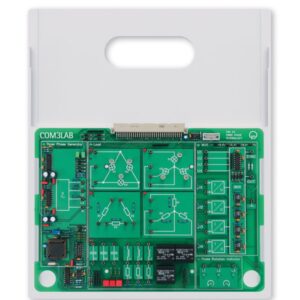
Opis
The experiments are carried out using industrial-design machines. All the test machines possess a special base for connecting the Machine test system 1.0. The testing system can be used to record the characteristics of the machines under test. Power for the machines is supplied either via the mains or by special laboratory power supplies.
Objectives
- Protective measures and electrical safety
- Setting up electrical machines and putting them into operation
- Use of starting circuits
- Assessment of electrical machine characteristics
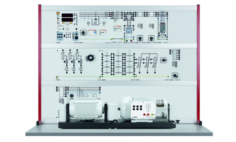
Asynchronous machines are used as motors and generators for low power applications of up to 2.5 MW. When used as generators in wind turbines, asynchronous generators operate withoput additional auxiliary energy. In the training system E2.3.4 Three-phase induction machines 1 kW, motor characteristics (operating quadrants I and III) and generator characteristics (operating quadrants II and IV) are recorded in conjunction with a drive machine. Measurement of energy quanitites and efficiency round off the experiments described in the supplied literature. Braking mode can also be investigated using an asynchronous machine. The electro-mechanical principle behind it, so-called dynamic lowering, is used for lifting platforms.
Features
- In order to protect against overheating, the stator windings of the machines to be tested are equipped with temperature sensors
- Should overheating occur, the machine test system automatically shuts down the test machine, thus preventing any damage to it.
- The machines to be tested are equipped with an educationally designed terminal board with the winding configuration printed on it.
- The ends of all the windings are connected to the terminal board and can be accessed via 4-mm safety sockets
- Computer-supported acquisition of measurement data provides for meaningful measurement results.
- Machines in the 1 kW rating class have a powerful and realistic operating response
- In comparison to smaller machines, their characteristics display distinctive features related to the design.
The complete equipment set is equally suitable for student experiments in laboratories with low voltage supplies (400 V three-phase) and for setting up on a mobile trolley for demonstration by teachers in a classroom. The procedures for the experiments are provided in a printed manual.
The target group is made up of commercial apprentices and students of electrical machine construction. The course offers experiments at an intermediate level and also allows for the necessary insight into machine behaviour for scientific interpretation at undergraduate level.
Topics for motor operation
- Design and function
- Operating characteristics
- Starting: slip-ring rotors, deep-bar squirrel cage rotors, star-delta starting, switching via a starting transformer, stator resistance starting circuit
- Braking: regenerative braking, DC braking, dynamic lowering circuit
- Power performance of an ideal rotating field machine
- Power flux
- Locus (Heyland circle) diagram
- Experiment without any load
- Short-circuit load experiment
- Variable speed asynchronous motors: pole switching, Dahlander circuits, speed control via modification of slip
- Slip-ring rotors
Topics for generator operation
- Design and function
- Fundamentals of three-phase generators
- Characteristics in generator operation
- Self-excitation of an asynchronous generator
- Current locus diagram
- Voltage stability
- Applications: operation in a constant-voltage, constant-frequency network, isolated operation
- Power performance
Similar to illustration
| 732 81 | Squirrel cage motor 400/690 1.0 | 1 |
| 732 804 | Squirrel cage motor 230/400 1.0 | 1 |
| 733 03 | Slip ring motor 1.0 | 1 |
| 732 94 | Squirrel cage motor D 1.0 | 1 |
| 732 96 | Squirrel cage motor SW 1.0 | 1 |
| 732 98 | * Multi-function machine 1.0 | 1 |
| 731 50 | Star-delta starter | 1 |
| 731 47 | Star-delta switch | 1 |
| 731 48 | Star-delta reversing switch | 1 |
| 731 49 | Reversing switch | 1 |
| 731 55 | Pole reverser, Dahlander | 1 |
| 731 57 | Pole reverser SW | 1 |
| 732 99 | Rotor starter 1.0 | 1 |
| 733 10 8 | Resistive load 1.0 | 1 |
| 733 11 8 | Capacitive load 1.0 | 1 |
| 733 05 | Blocking Gear Mechanism 1.0 | 1 |
| 731 391 | Squirrel cage fault simulator | 1 |
| 731 51 | Soft starter 0.3 /1.0 | 1 |
| 745 561 | Power circuit breaker module | 1 |
| 732 83 | Motor protection switch, 1.6-2.4 A | 1 |
| 531 600 | Insulation tester Metriso C | 1 |
| 531 282 | Multimeter Metrahit Pro | 3 |
| 727 12 | Power factor meter | 1 |
| 732 689USB | Machine test system 1.0 | 1 |
| 728 421 | CBM10 MOMO/FCCP | 1 |
| 726 75 | Three-phase supply unit with ELCB | 1 |
| 726 09 | Panel frame T130, two-level | 1 |
| 732 56 | Coupling 1.0 | 1 |
| 732 57 | Shaft end guard 1.0 | 1 |
| 732 581 | Coupling Guard 1.0 transparent | 1 |
| 501 45 | Connecting lead, 19 A, 50 cm, red/blue, pair | 5 |
| 500 59 | Safety bridging plugs, black, set of 10 | 2 |
| 500 591 | Safety bridging plugs, yellow/green, set of 10 | 1 |
| 500 851 | Safety connecting leads, 32 A, set of 32 | 1 |
| 500 852 | Safety connecting leads, 32 A, yellow/green, set of 10 | 1 |
| 566 821L | LIT: Squirrel Cage Motor 380/660V 1.0 (in German) | 1 |
| 566 821S | LIT: Squirrel Cage Motor 380/660V 1.0 (in German) | 1 |
| 566 822 | * LIT: Squirrel Cage Motor 380/660V 1.0 (in English) | 1 |
Articles marked with * are not essential, we do however recommend them to carry out the experiment.

