E 2.5.3.2 Podstawy przetworników częstotliwości
Opis
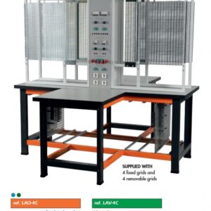
This laboratory practical utilises training panels in panel frames. The power is supplied to the frequency converter directly from the mains (mains voltage, 230 V).
Objectives
- Protective measures and electrical safety
- Components of a frequency converter with variable voltage link
- Setting parameters for frequency converters
- Gaining skill in measurement techniques
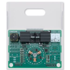
This equipment set offers an insight into the circuitry of frequency converters with variable voltage link. Measurements are made on the components of a frequency converter especially designed for educational purposes. The experiments use a static electronic load, which facilitates the evaluation of current and voltage curves. A rotating field with variable frequency is also investigated. The following components can be accessed:
- Input bridge rectifier with link capacitor
- Brake chopper
- Power inverter
Students work in the power engineering lab with mains voltage. Experiments procedures are contained in a printed manual.
The experiments are designed for intermediate and advanced levels.
Topics
- Rotating field and space vectors
- Feeding a sinusoidal signal from the normal three-phase mains network
- Representation of space vectors
- Generation of a rotating field from a DC voltage
- Putting a converter into operation
- Fault-free activation of the mains voltage
- Activation of the input rectifier
- Switching off the converter
- Discharging the buffer capacitor
- Investigation of input rectifier
- Response with zero-delay angle setting, Cl = 00
- Control characteristic
- Loading
- Control via external control voltage
- Investigation of output inverter
- Control of individual power transistors
- Generation of rotating field
- Loading with resistive load
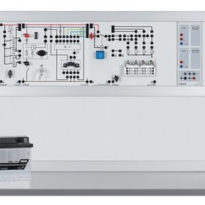
Similar to illustration